MELAL
Business Hotel
Project Location: Tehran, Iran
Role: Freelance Architectural BIM Modeller
Project Status: Under Construction
Period of Contribution: 10/2019 – 11/2021
Client: Melal Hotel Group, Investment Department
Credits & Ownership: Collaborative, Third-Party Ownership
—Portfolio Note:
The material shown on this page is a selective, simplified, and non-buildable representation of a collaborative project. More information is available at the end of this page and in the Legal Notice & Copyright section.
—Project Overview:
Mellal is a 26-story mixed-use hospitality development located near Vanak Square in Tehran’s central business district. It has a total built-up area of 65,346 sq. m and features 373 guest rooms, broken down as follows: 18 single rooms, 256 standard rooms, 88 junior suites, 9 executive suites, and 2 presidential suites. The design integrates high-end hospitality functions with advanced architectural and structural solutions. I contributed during the execution planning phase, with a primary focus on architecture BIM modelling. This involvement came after a decade-long project pause caused by municipal permission conflicts related to traffic issues.

—Context & Technical challenges:
The project’s structure combines a reinforced concrete core with a steel frame, originally designed about a decade earlier and modelled in an older version of Tekla by the structural team. The foundation and several structural elements had already been erected before the pause. When the project restarted, our team took on architecture modelling at LOD 400 in Revit. The main technical challenges arose from the legacy Tekla data, including outdated modelling conventions, mismatched object intelligence, lost or flattened parameters, and structural elements appearing as “dumb geometry” without semantic meaning. Additional issues involved inconsistent profiles, materials, and naming logic. These were especially problematic given our team’s lack of prior experience with this hybrid structural system. On the organizational side, frequent client-requested design changes on the outdated base documents added complexity and required ongoing adaptations.

The diagram presents three orthographic axonometric views (West, South, and East) of the Melal Business Hotel, illustrating the vertical organization and spatial distribution of its core functions.
—Role & Modelling Scope:
I worked as an architectural BIM modeller as part of the broader BIM team. My core responsibilities encompassed high-LOD architectural modelling, detailed façade systems modelling, creation of parametric families, and using Dynamo for automating repetitive tasks. The scope also included generating issued drawings for both tender and construction stages, along with developing and implementing drawing standards and view templates. I interfaced directly with the architecture and MEP disciplines to ensure alignment. In terms of decision-making, I was fully responsible for technical choices related to modelling approaches, parametric family setups, Dynamo automation, and the application of drawing standards within my assigned areas. I also contributed collaboratively to strategies for façade detailing, resolving coordination issues, and preparing/reviewing drawings as part of the team effort. Coordination-related work was reviewed jointly with structural and MEP teams through multidisciplinary BIM processes.
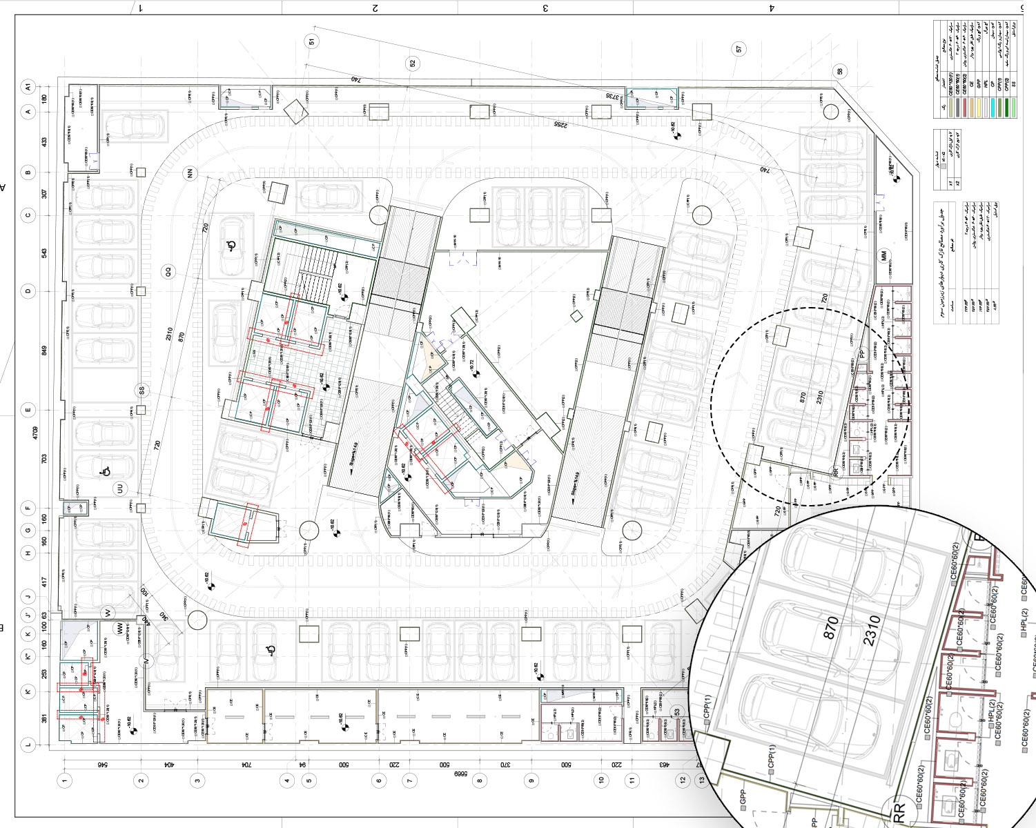
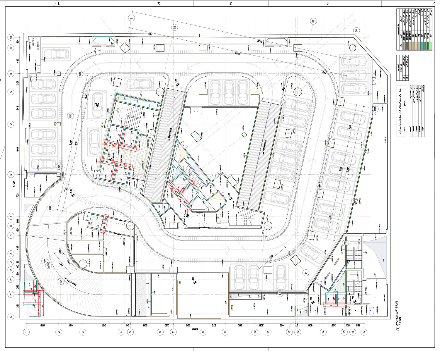
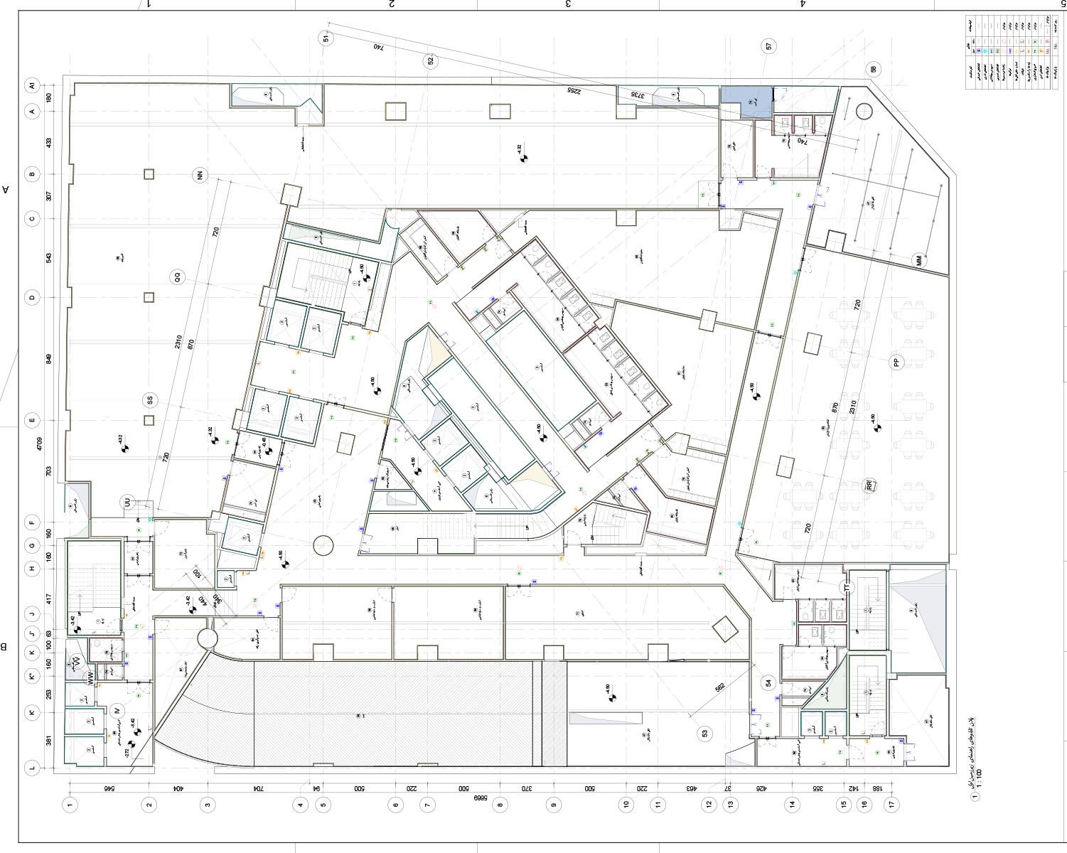
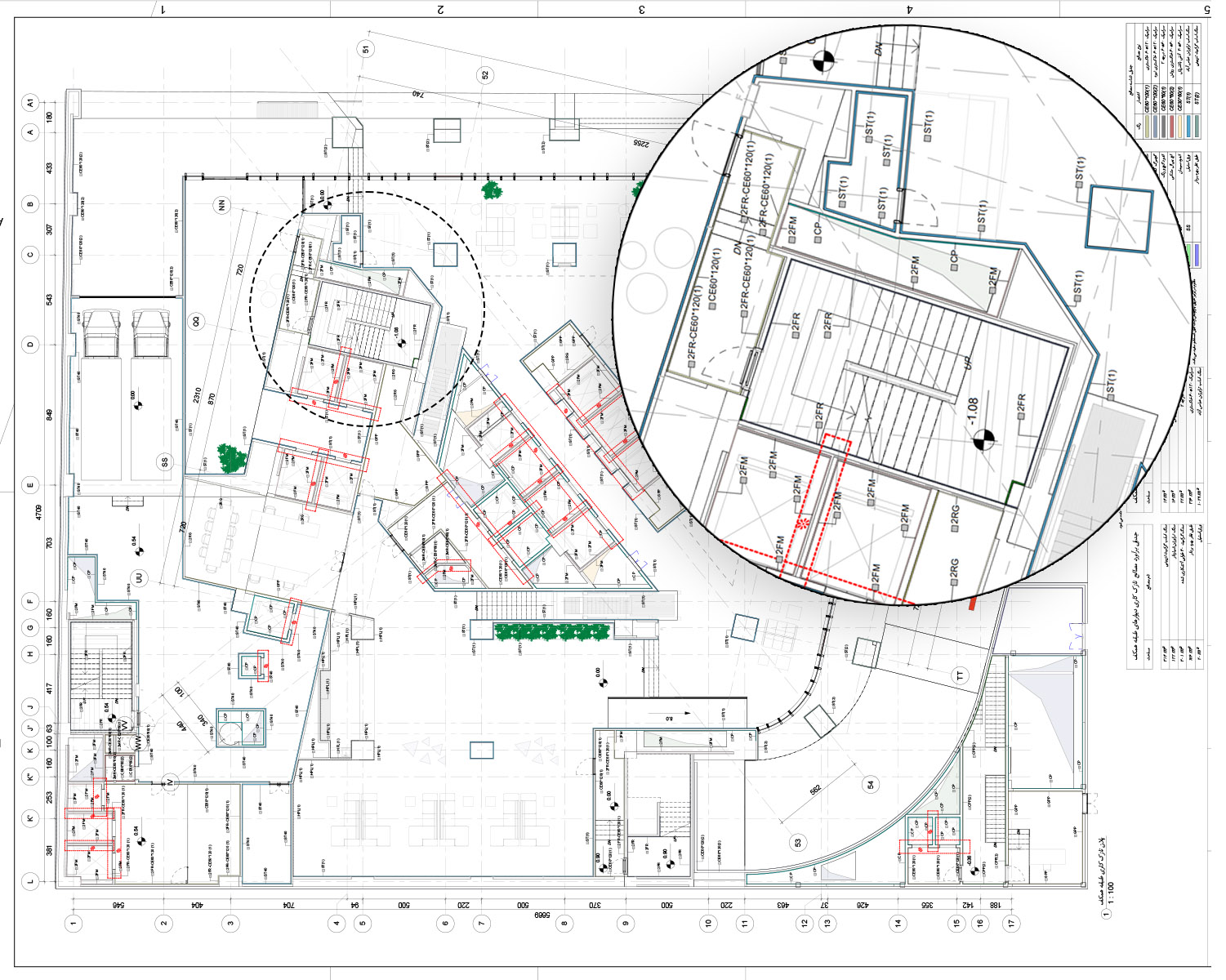
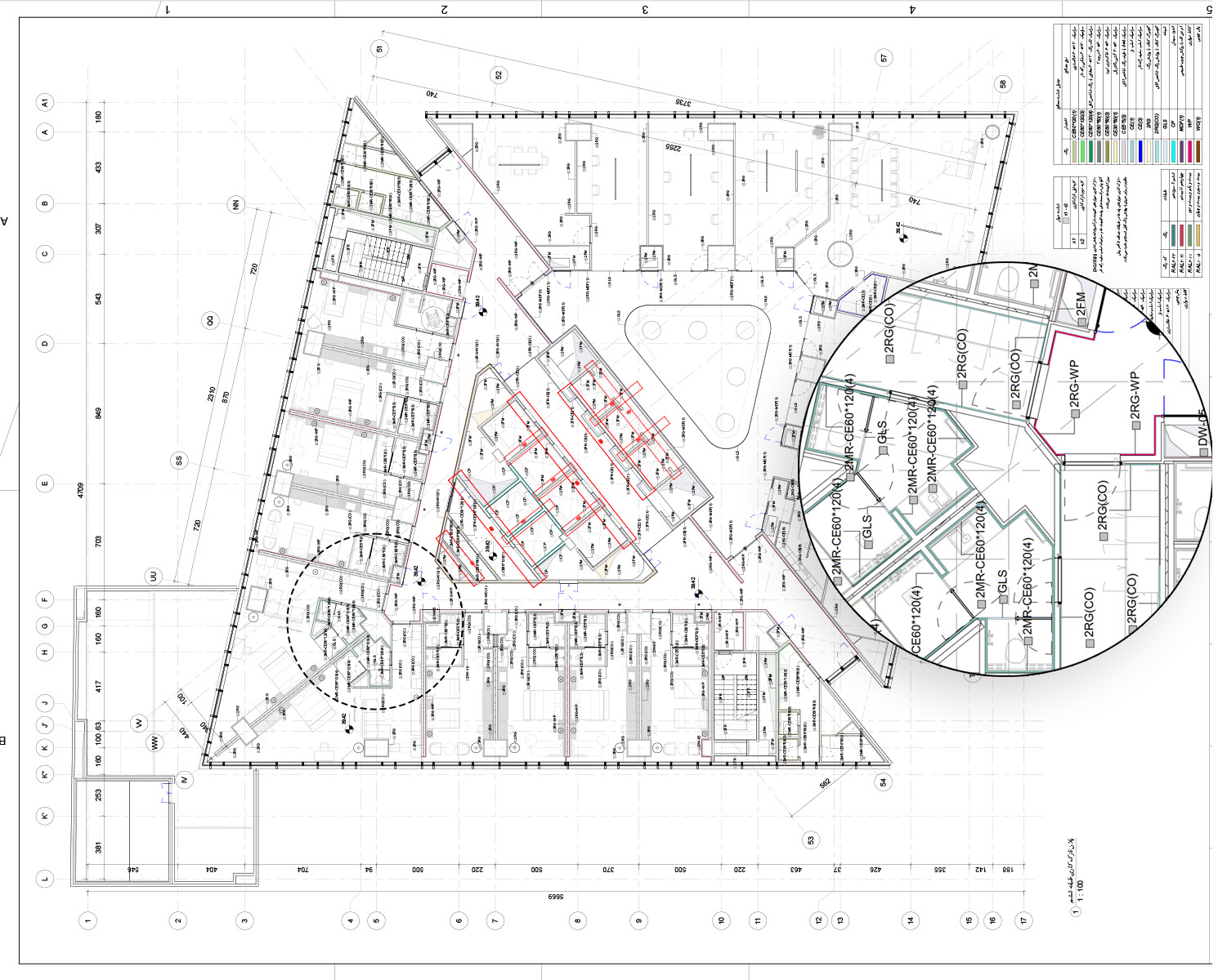
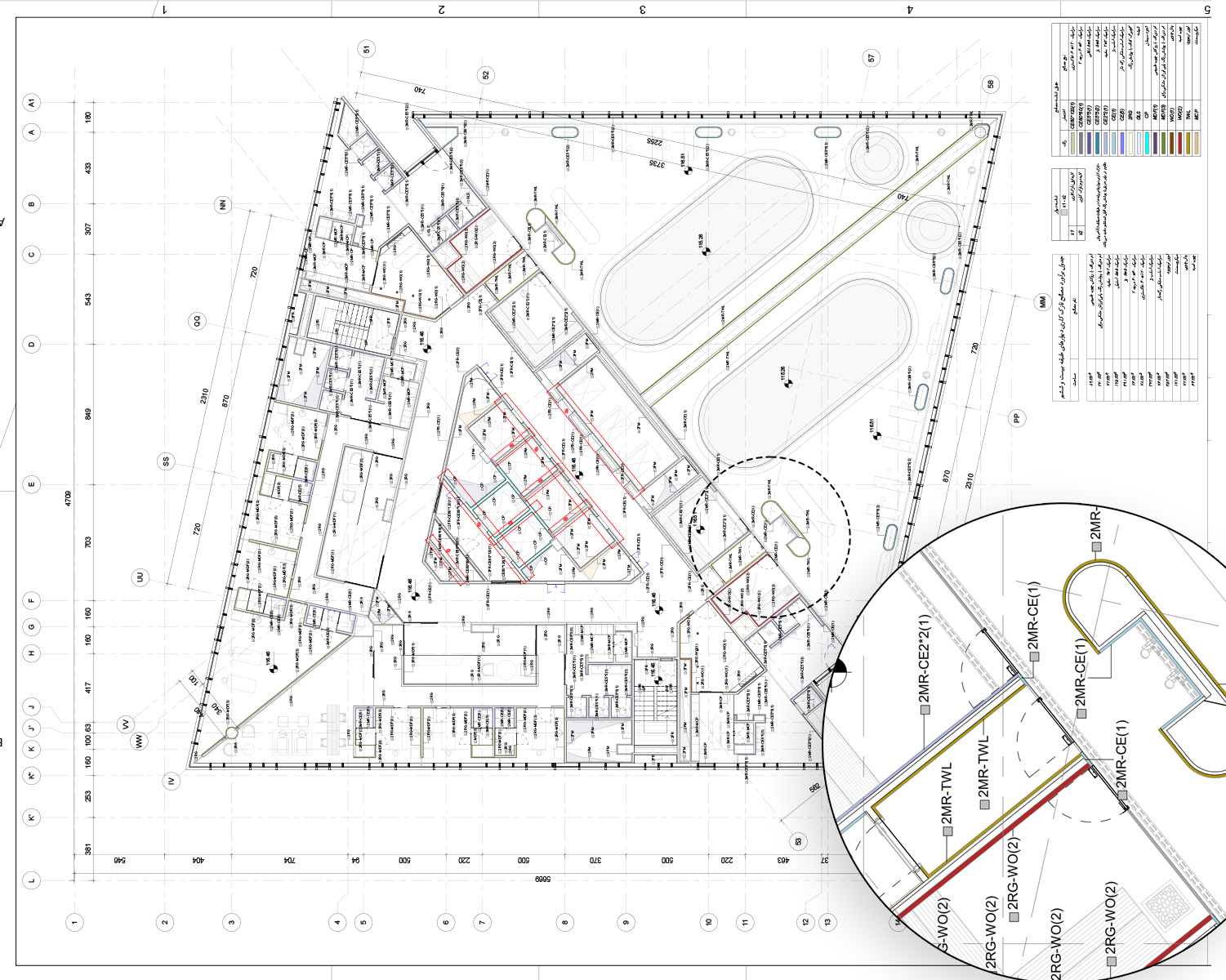
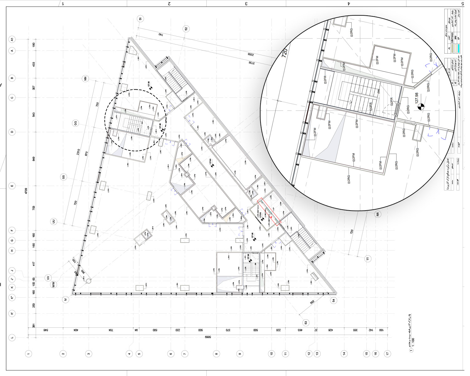
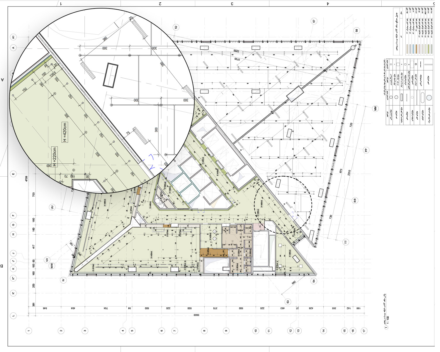
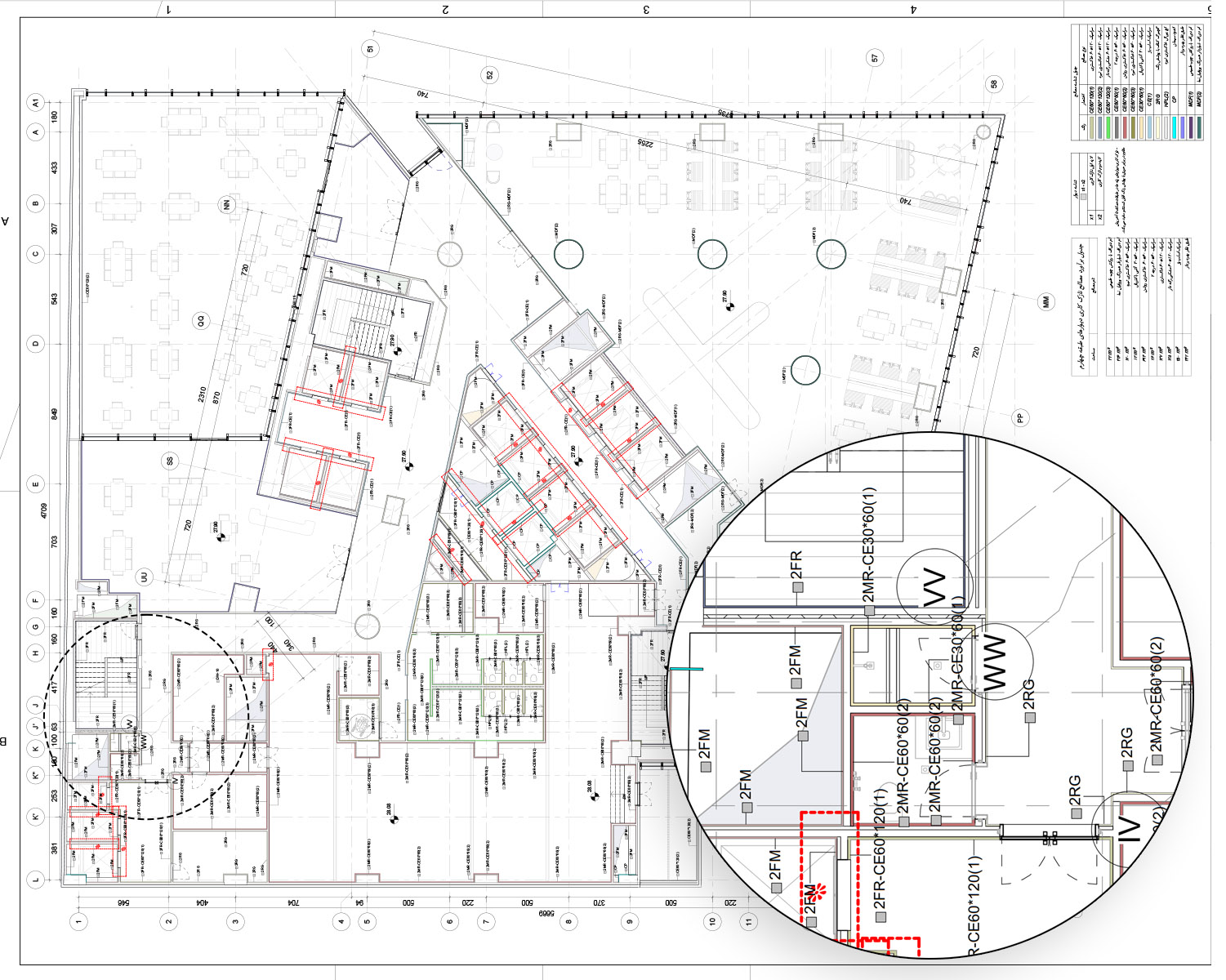
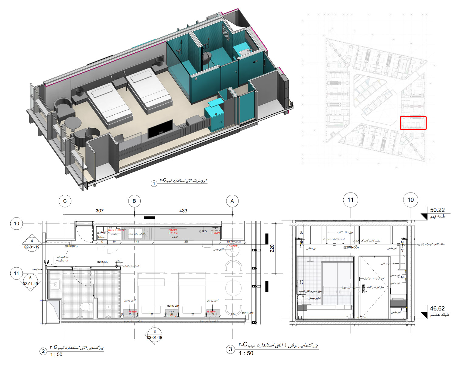
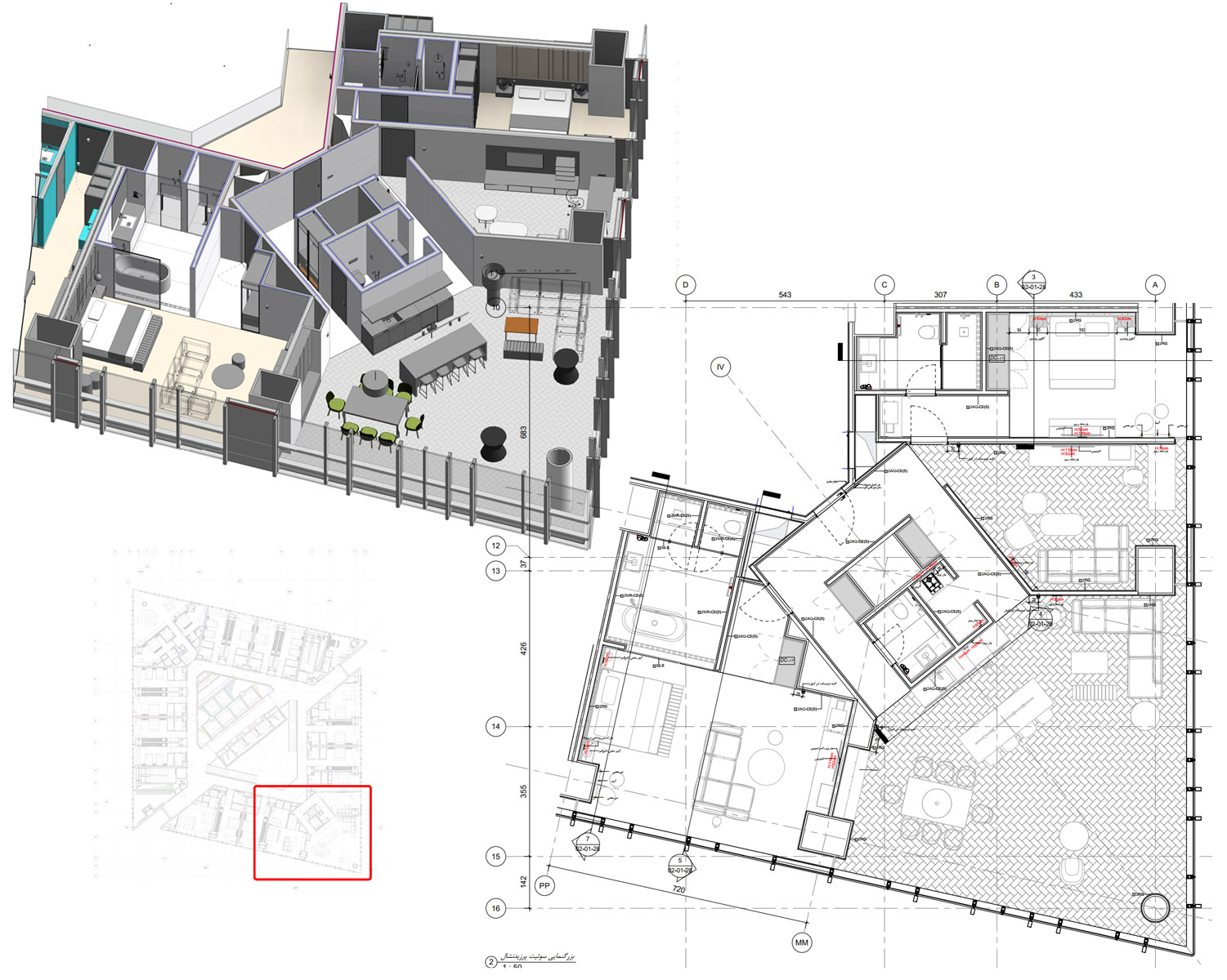
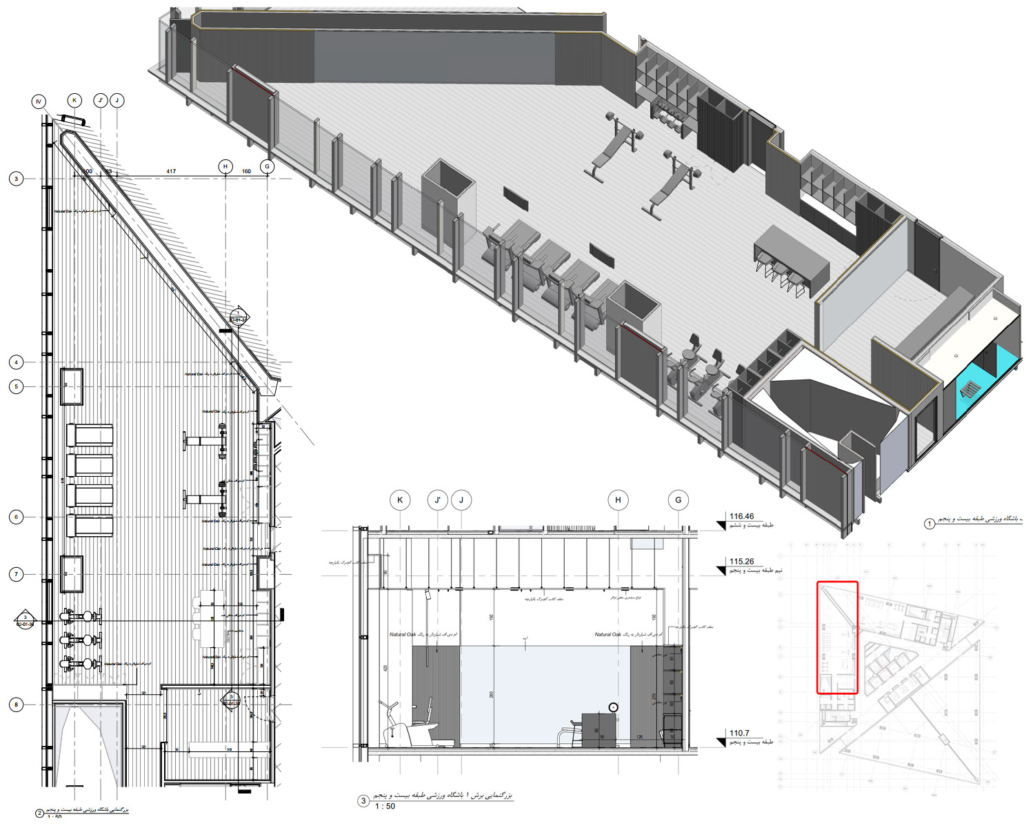
Below are sample technical floor plans from the project, demonstrating the spatial organization and architectural detailing of the finalized documents. — 10 Documents
—Coordination & Collaboration:
When I joined, the project was resuming after its long pause, starting with key inputs such as 2D CAD documents, existing permits, initial concept 3D models, and mood boards for reference. My first tasks centered on architecture BIM modelling, evaluating the legacy Tekla structural model, performing data remediation for seamless Revit integration, creating high-LOD elements, and engaging in iterative coordination cycles. Overall coordination adhered to BIMForum/AIA LOD specifications and ISO 19650 principles for information management and clash resolution. This involved federating discipline-specific Revit models (architecture, structure, MEP) using shared coordinates for precise alignment. Navisworks served as the primary tool for regular clash detection. Changes and conflicts were identified through automated hard/soft clash runs, supplemented by visual inspections and model audits. Resolution followed an iterative process: assigning clashes via reports to responsible disciplines, making updates in native Revit files (such as rerouting or adjustments), and re-federating models until achieving zero critical clashes at LOD 400 handover.
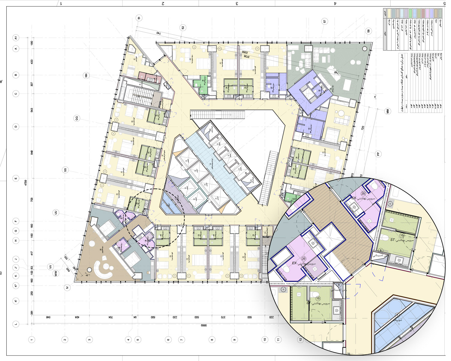
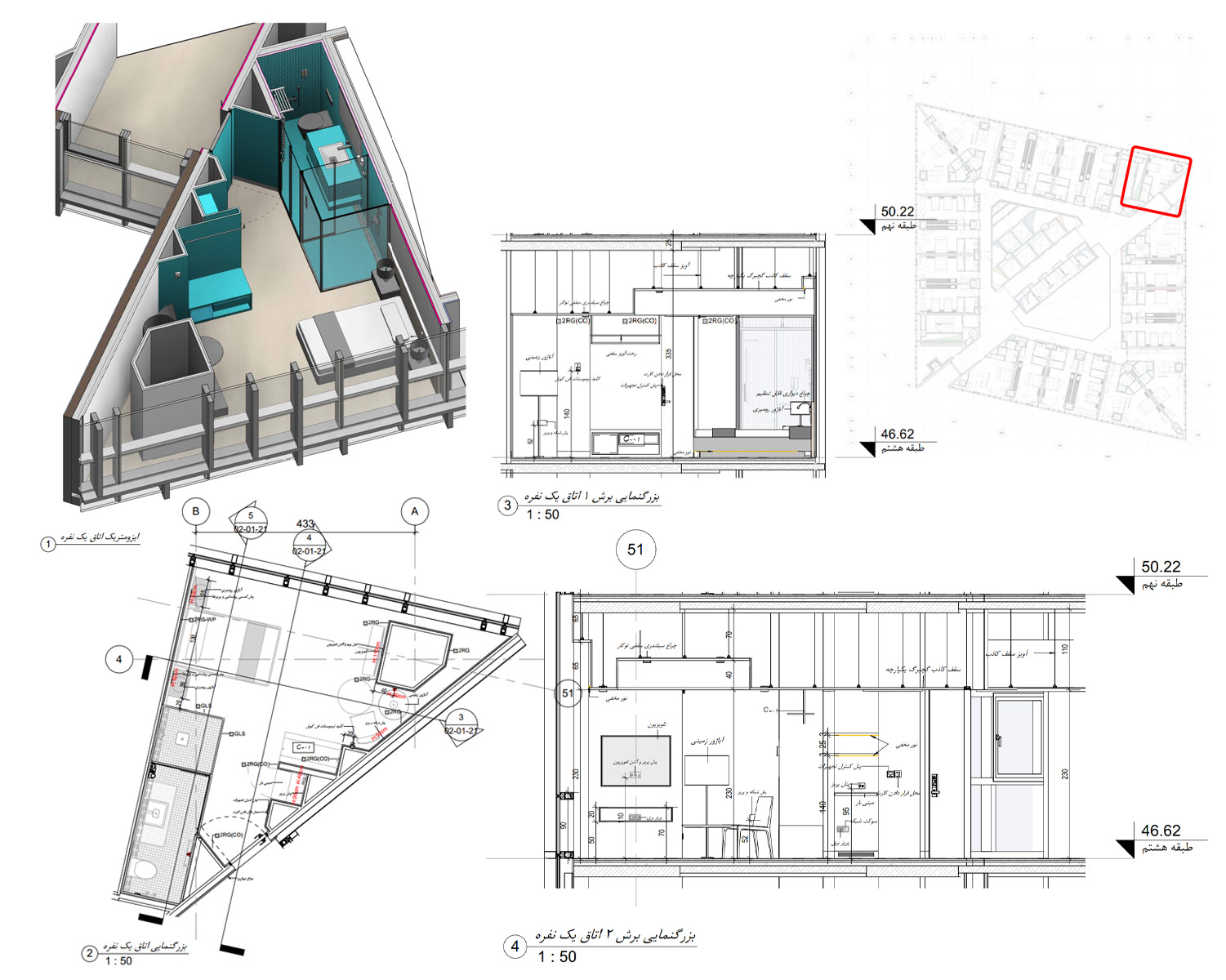
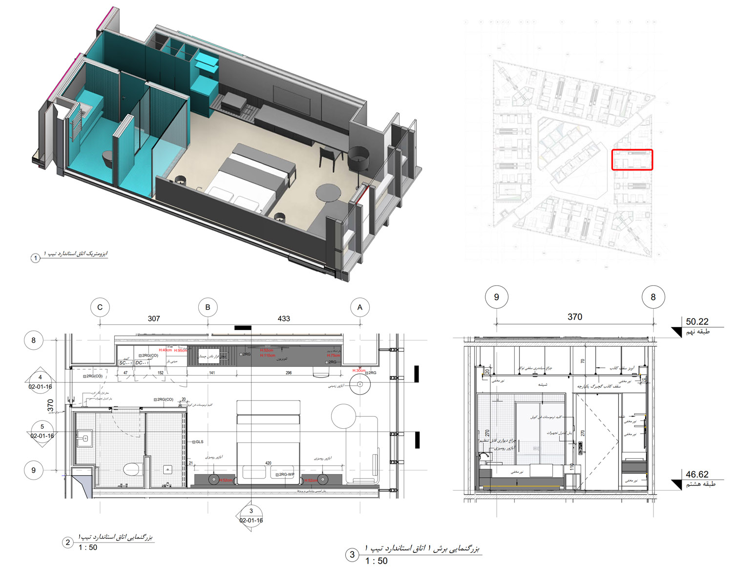
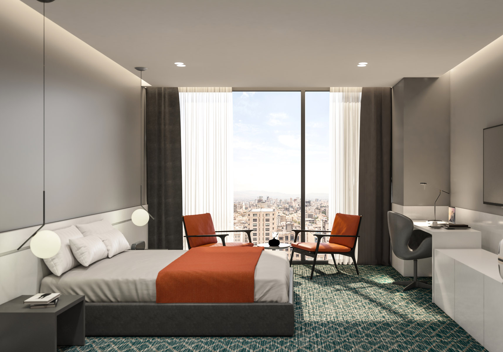
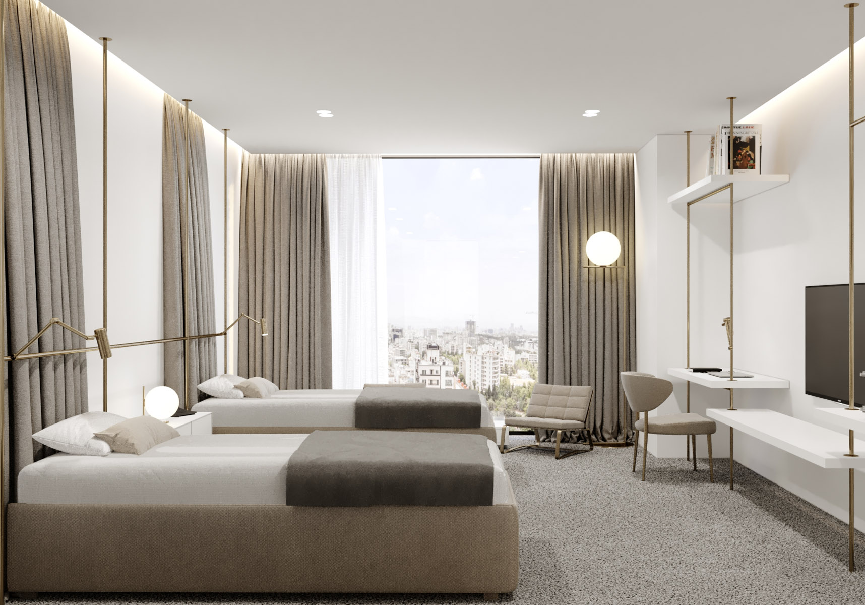
Below are callout sheets highlighting the design of various rooms and spaces within the project. —5 Documents
—Constraints & Responsibilities:
Key constraints shaping the work included tight time and budget limits due to the project restart, as well as the need to comply with pre-existing regulatory approvals and permissions. Areas outside my responsibility were concept design, overall architecture design, handling regulations and permissions, and any as-built modelling. I depended on inputs from others, particularly the structural team’s Tekla data and client-provided change requests. Assumptions that had to be respected centered on preserving LOD 400 semantic integrity and ensuring data interoperability through methods like IFC exports and shared coordinates. Quality assurance involved systematic model audits, detailed clash reports, and verification against established standards to maintain accuracy and consistency.
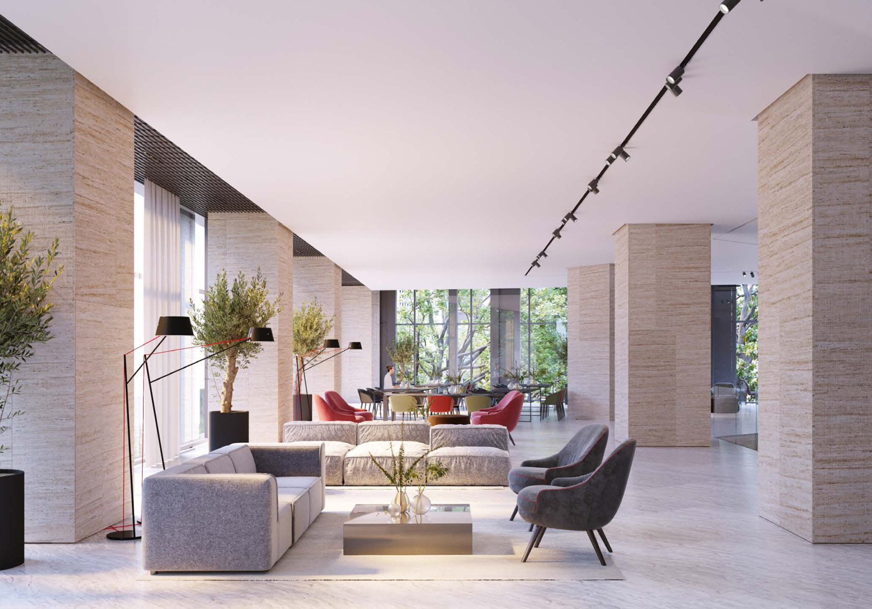
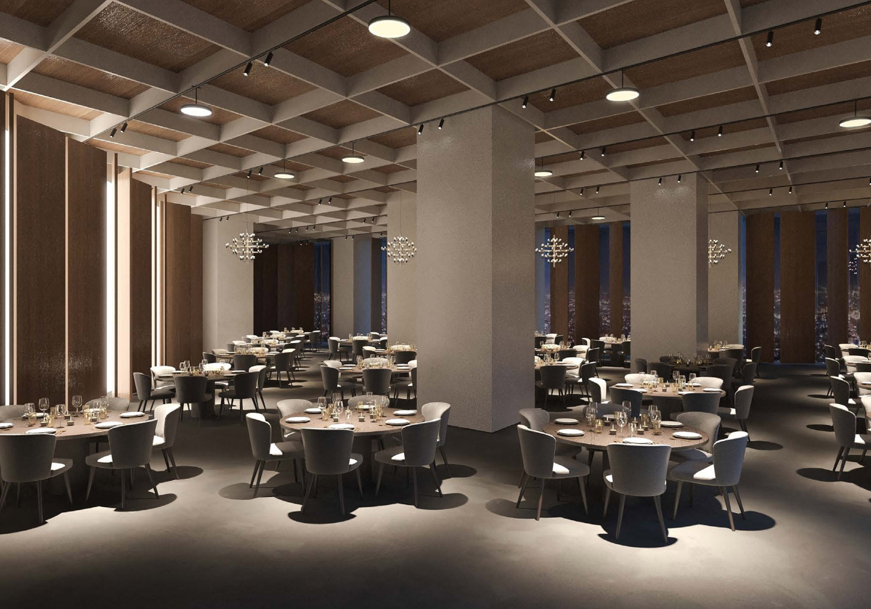
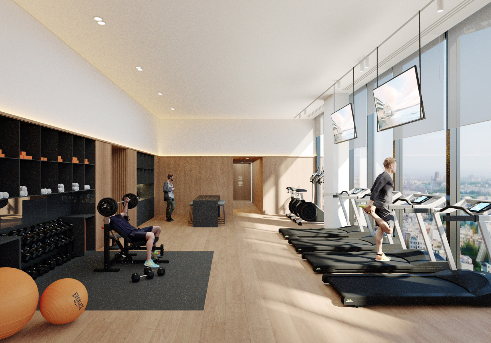
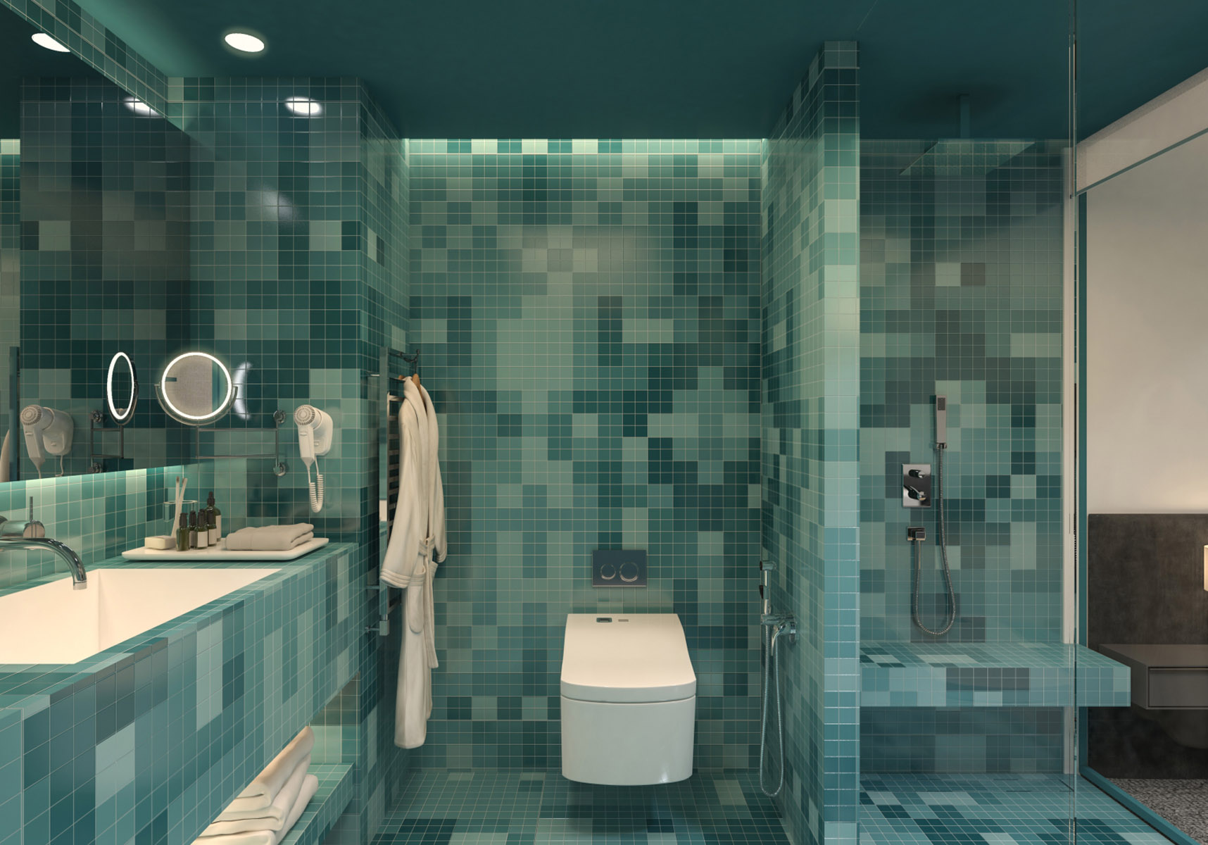
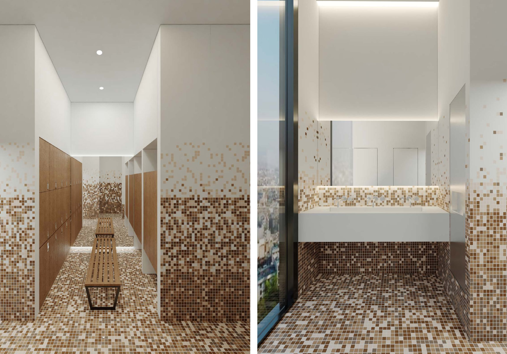
Every material and design element has been meticulously modeled within the BIM environment, ensuring a high level of accuracy and coordination. — 8 Visualizations

—Deliverables & Outcome:
The primary outputs from my contributions included LOD 400 Revit models for architecture, custom parametric families, Dynamo automation scripts, issued drawings for tender and construction purposes, and comprehensive coordination reports. These deliverables were utilized by downstream project teams to support fabrication, on-site installation, and detailed execution planning. By clarifying interfaces and preemptively resolving clashes in the digital environment, the work helped minimize potential on-site conflicts. Ultimately, it enhanced multi-discipline coordination and informed better decision-making, especially in managing legacy data within a restarted high-rise hospitality context.
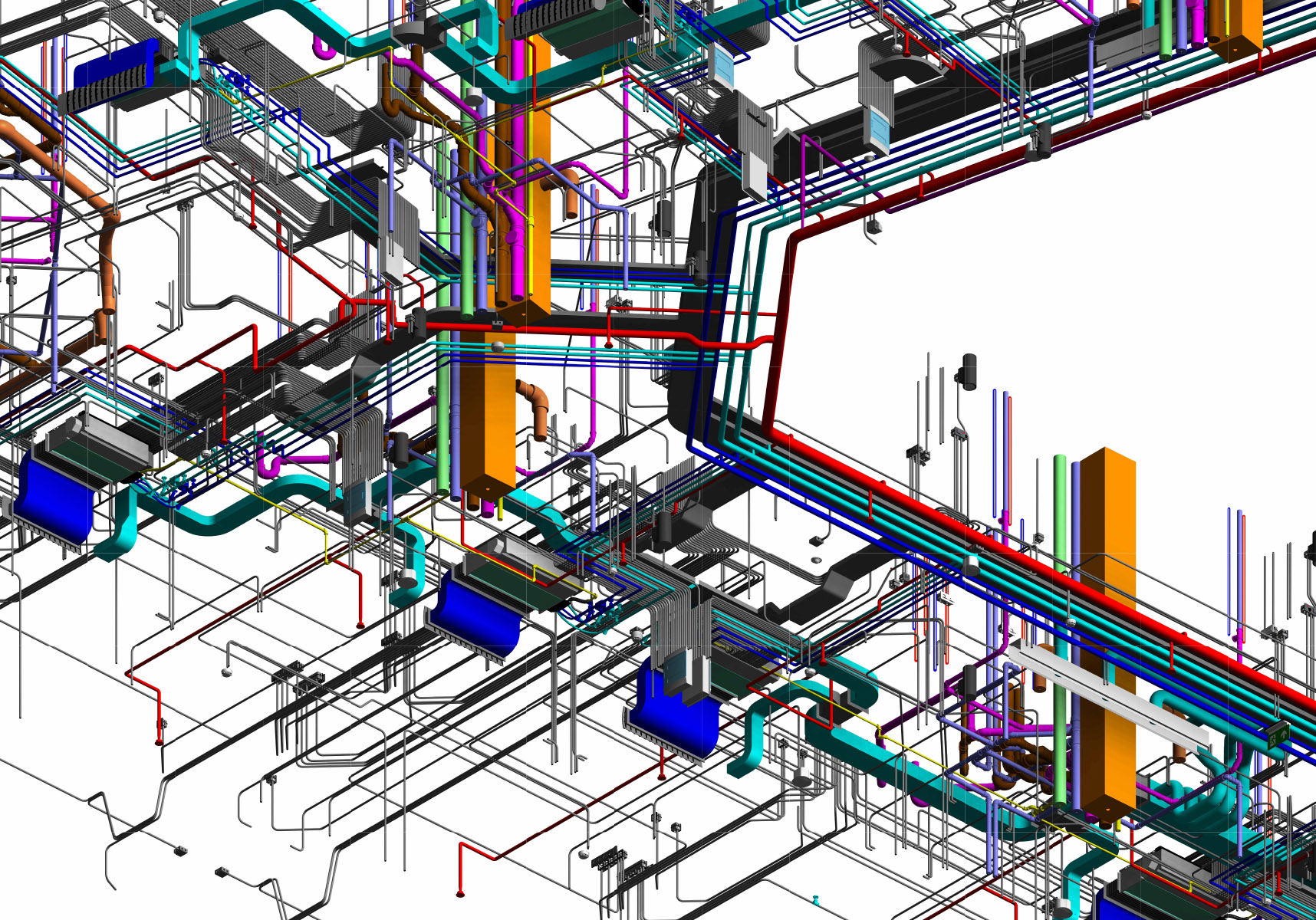
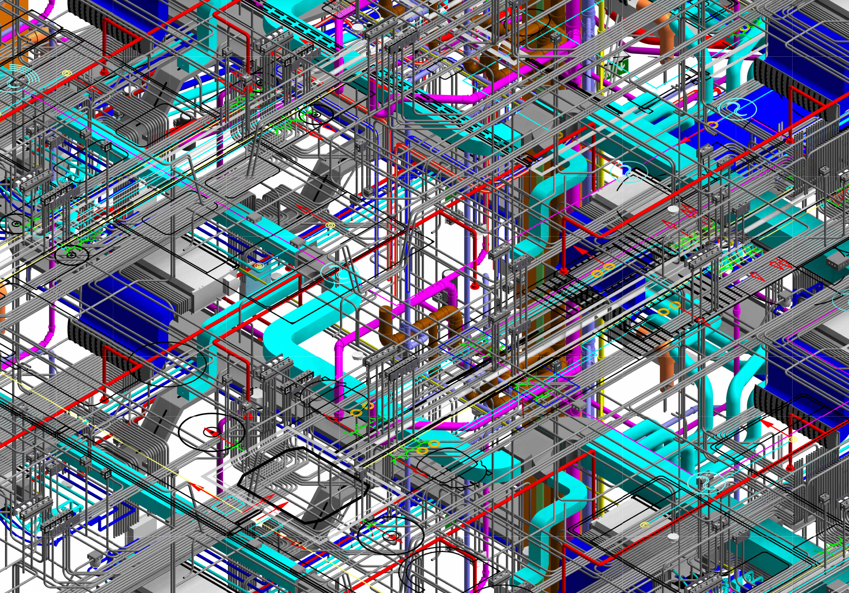
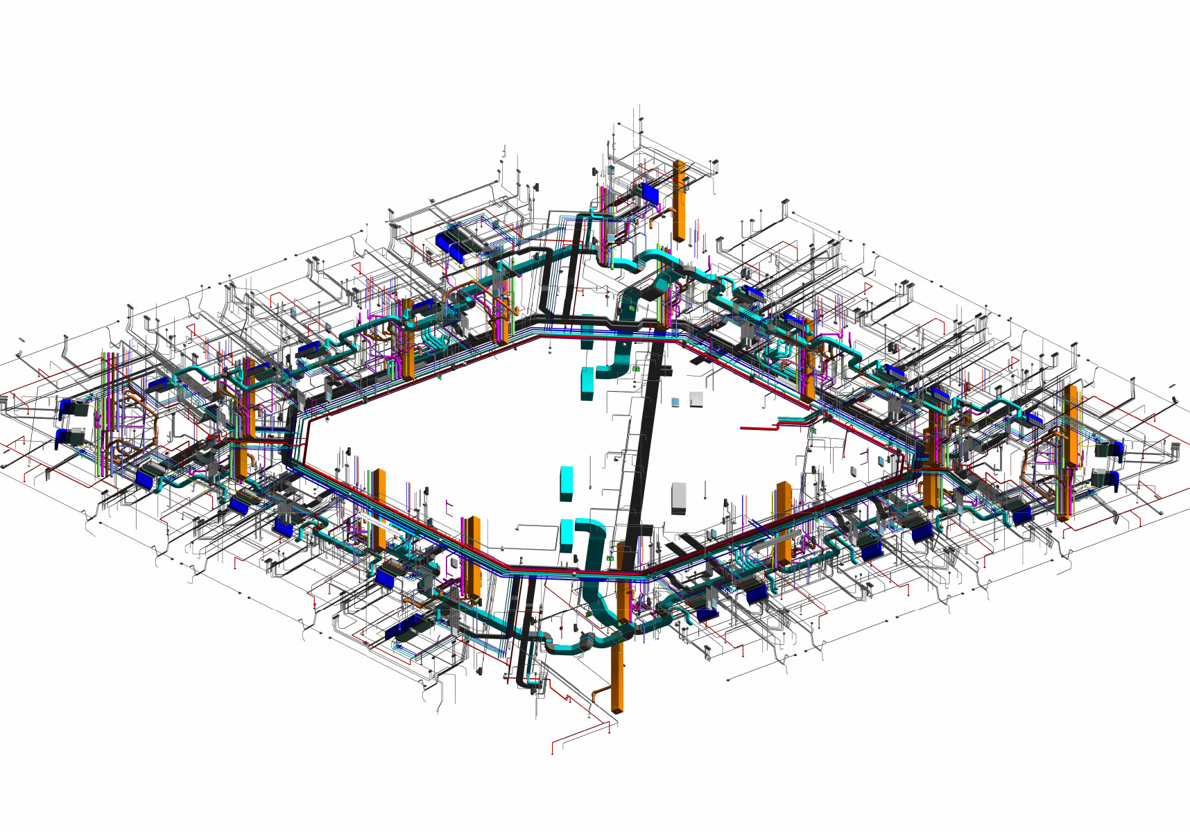
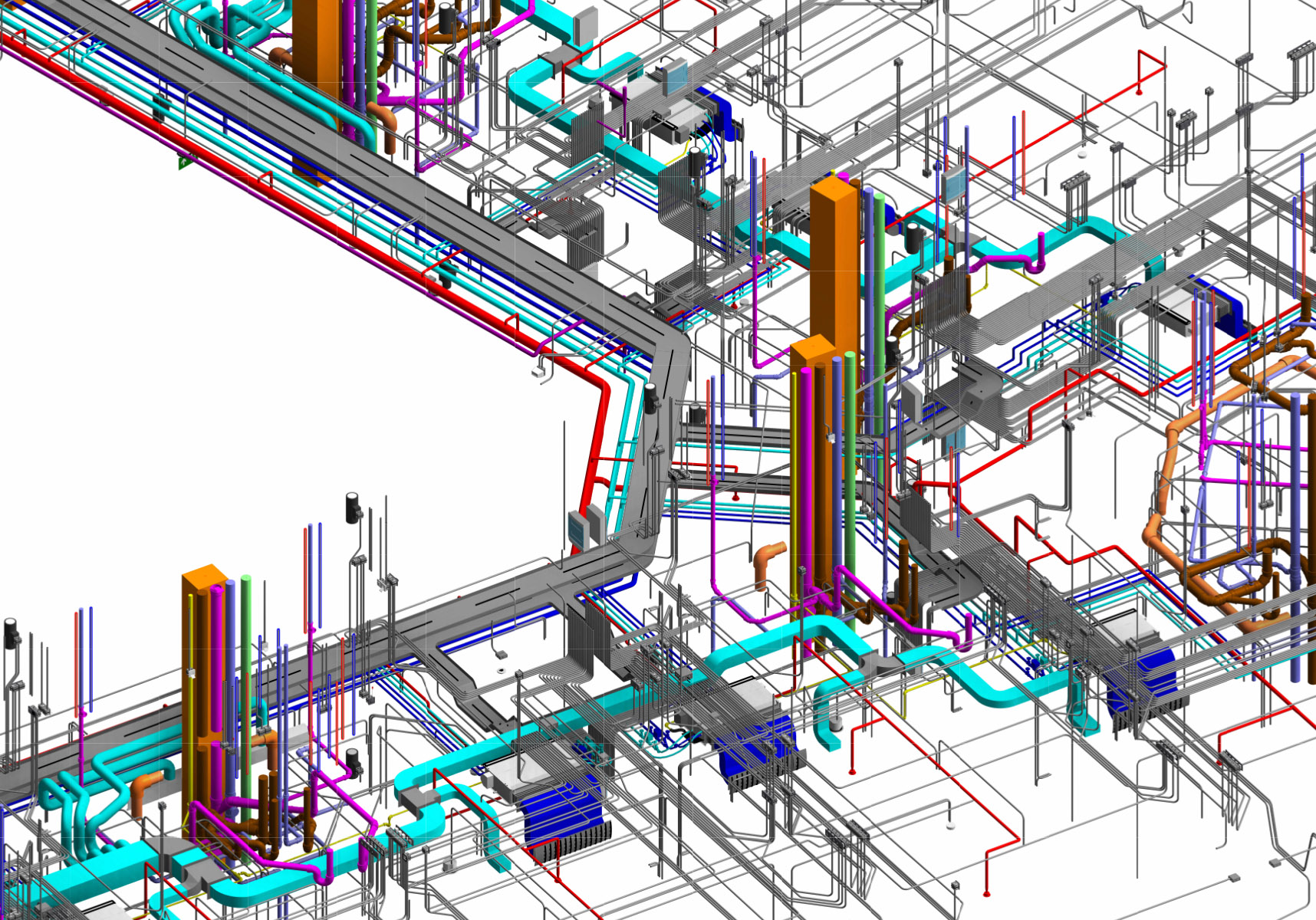
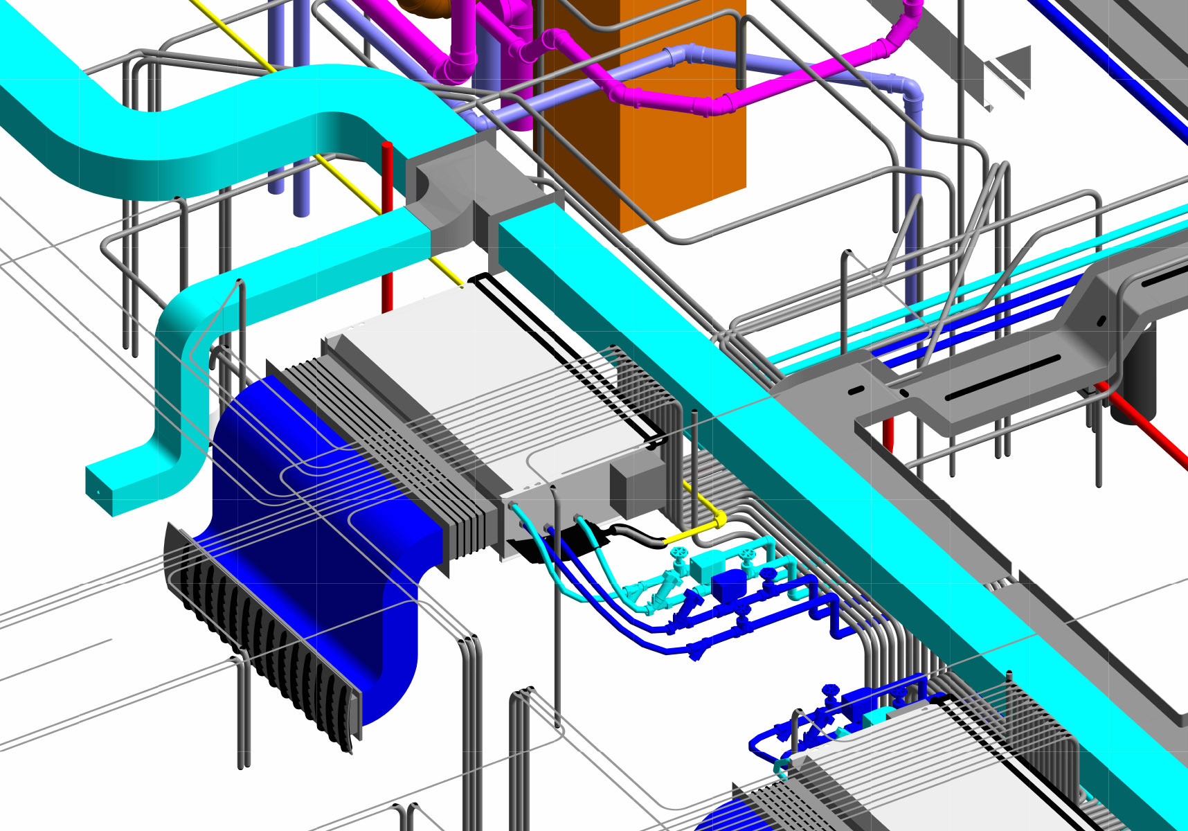
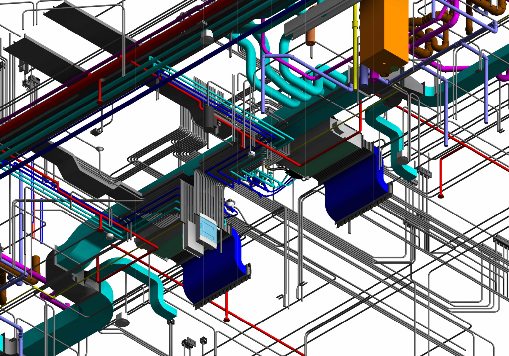
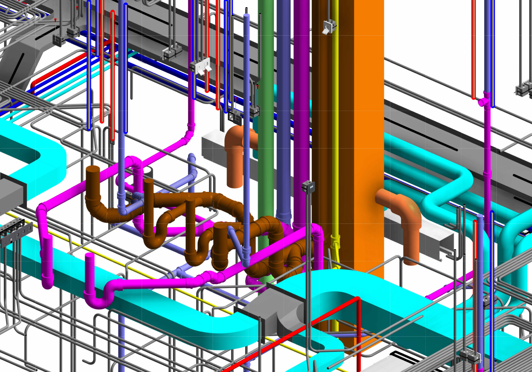
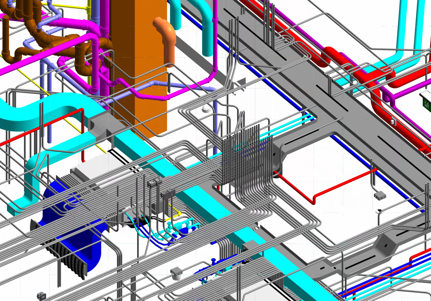
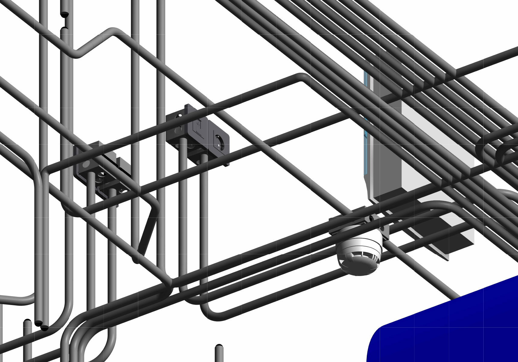
This isometric view showcases the fully integrated MEP systems modeled at LOD 350, ensuring precise coordination and constructability.

The model includes ventilation equipment such as FCUs, AHUs, and VRF units, along with a complete ductwork system featuring supply, return, and exhaust ducts with fittings, dampers, and insulation. The plumbing networks encompass hydronic systems, domestic hot and cold water, sanitary drainage, and venting, while utility piping includes gas lines, stormwater drainage, and fire suppression systems. Additionally, the fire protection system incorporates sprinklers, suppression equipment, and other fire safety components. The electrical systems are fully detailed with power distribution elements, conduits, cable trays, and panels, complemented by low-voltage components and lighting systems, including electrical devices, sensors, and lighting fixtures. This highly detailed BIM model facilitates clash detection, coordination, and seamless integration of all mechanical, electrical, and plumbing systems, optimizing project efficiency and accuracy. — 10 Visualizations of the MEP Model

—Reflection & Key Learnings:
In this project, I applied new workflows for legacy model integration, using Revit to revive and remediate the outdated Tekla-based hybrid structure (reinforced concrete core plus steel frame). This involved reverse-engineering techniques to restore semantic intelligence, repair lost or flattened parameters, update legacy profiles, materials, and naming conventions, and transform “dumb geometry” into fully intelligent BIM objects, effectively tackling the unfamiliar hybrid challenges. I also started to learn advanced multi-discipline coordination practices in Navisworks, aligned with BIMForum LOD 400 and ISO 19650 principles, to manage constant client-driven changes on old documents. Key takeaways included robust change management in federated models, improved interoperability between Tekla and Revit via IFC and shared coordinates, and the importance of early semantic enrichment for delivering accurate LOD 400 fabrication-ready models in paused or restarted scenarios.
11 Visualizations of the Structure Model.
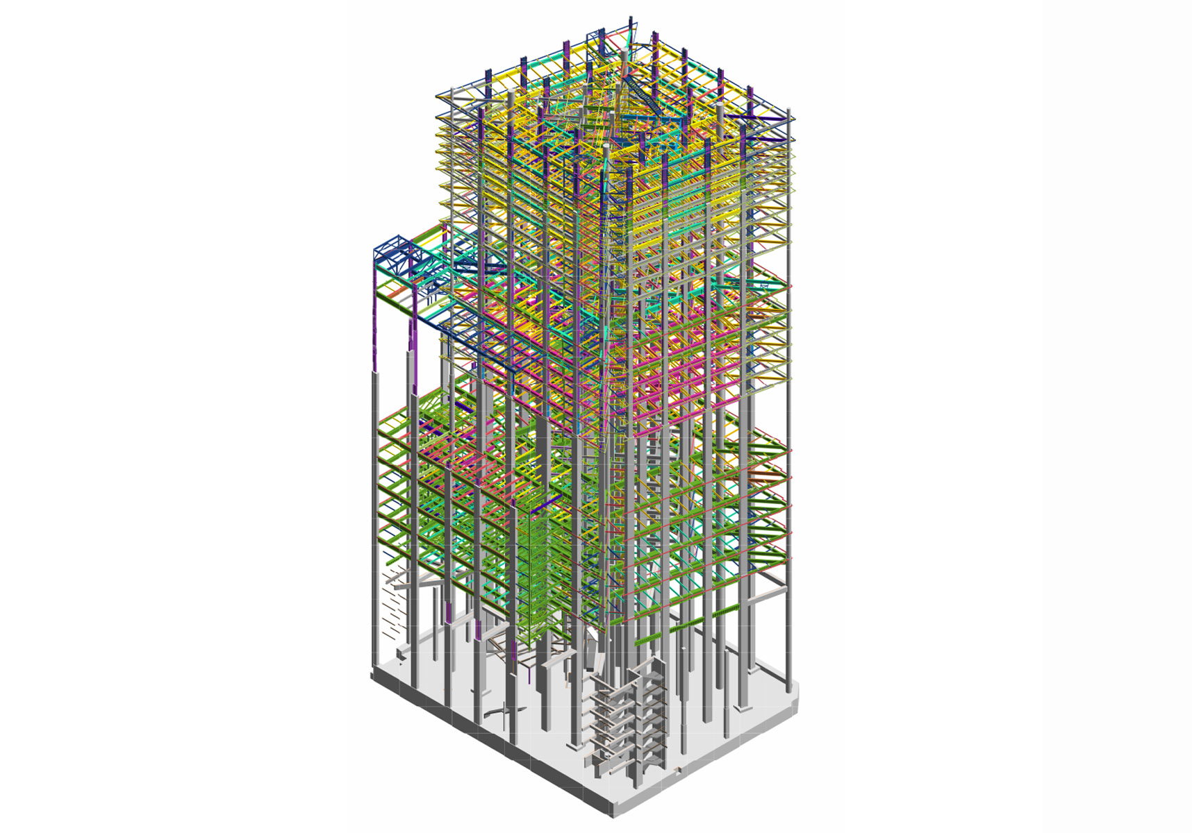
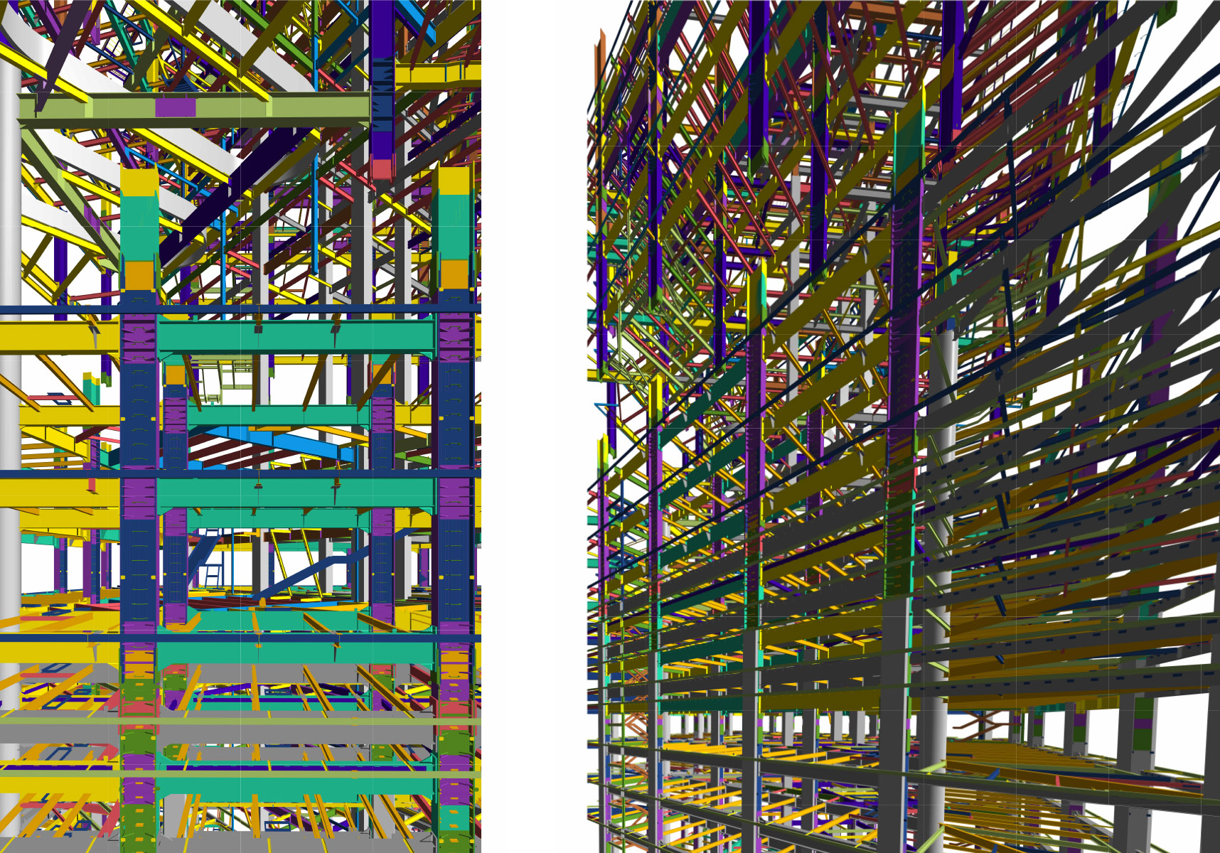
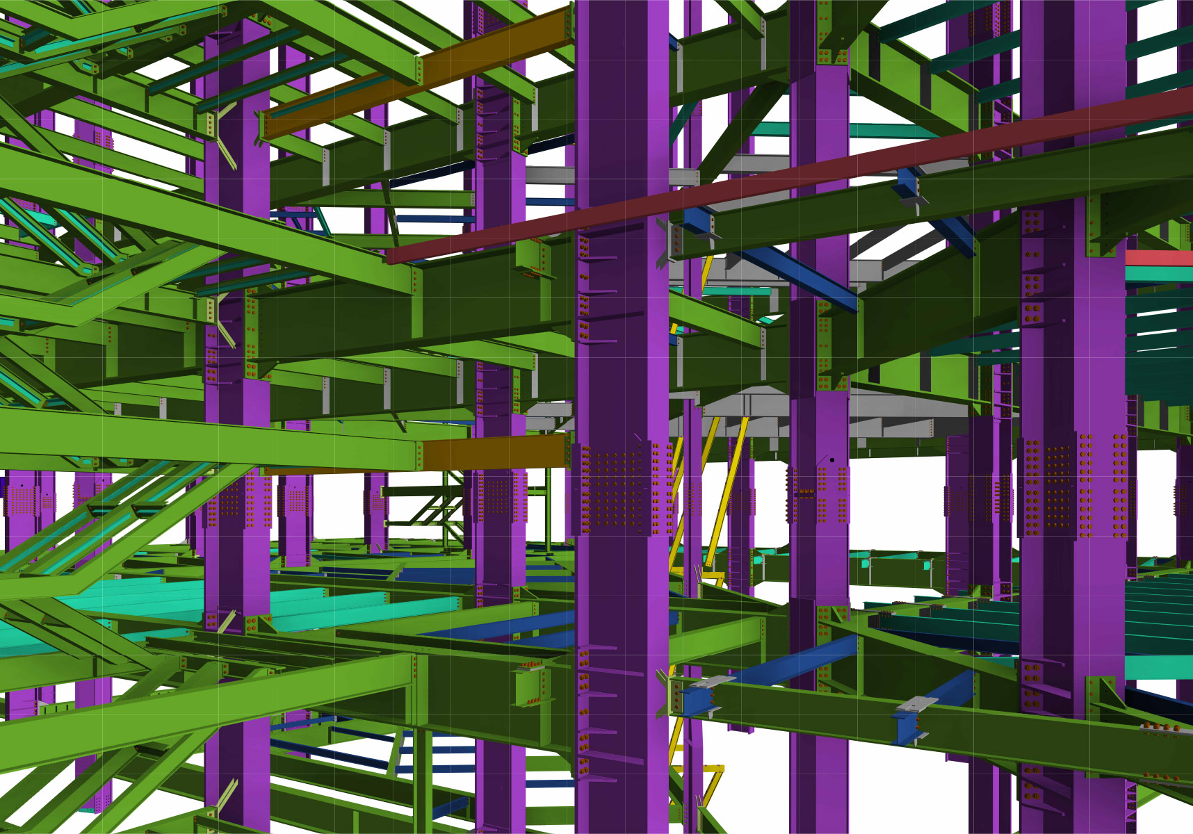
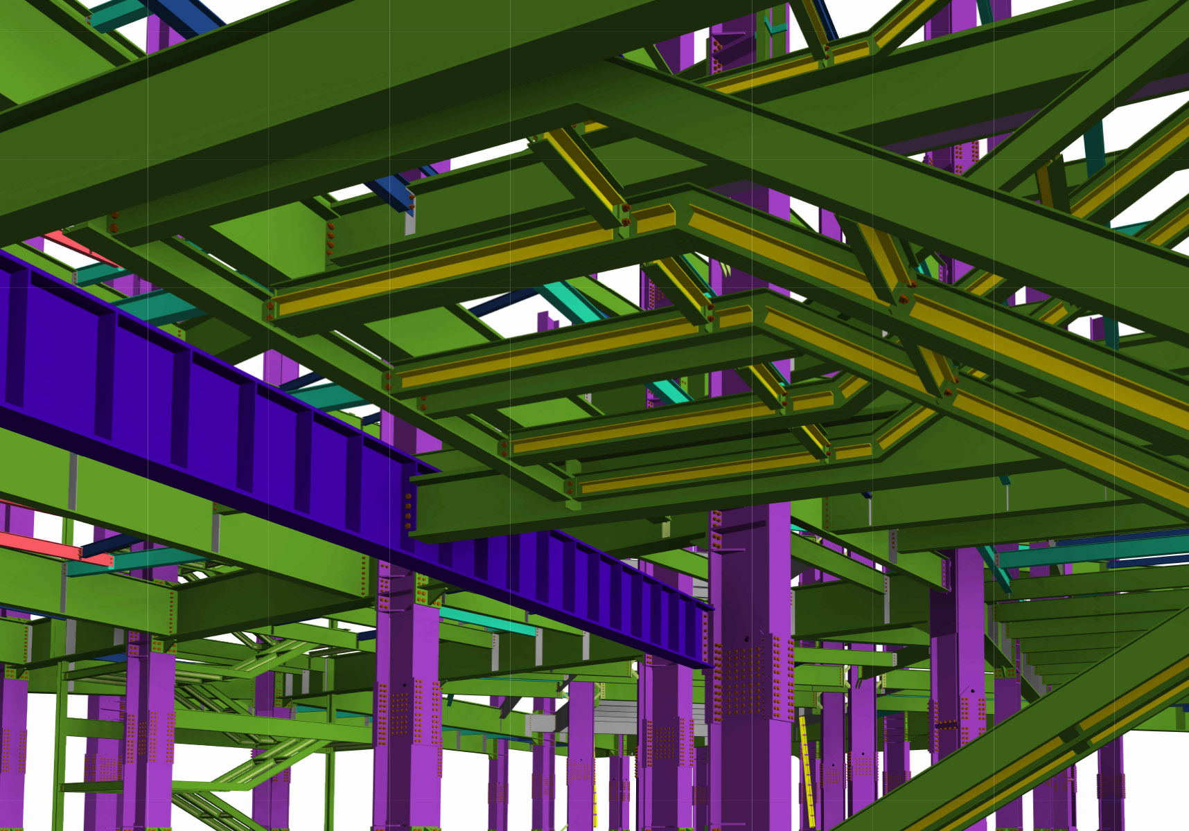
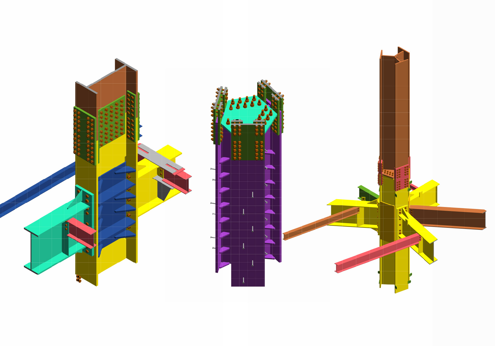
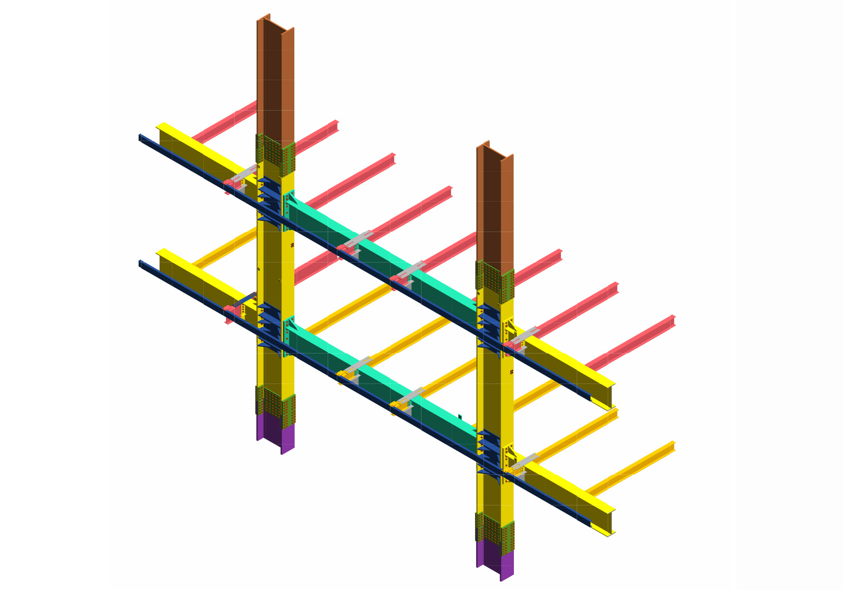
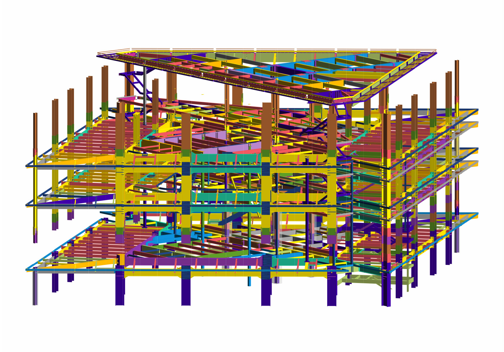
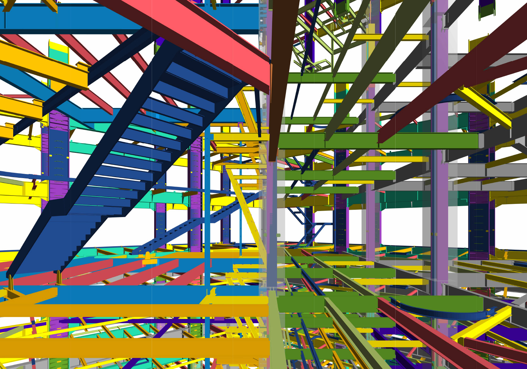
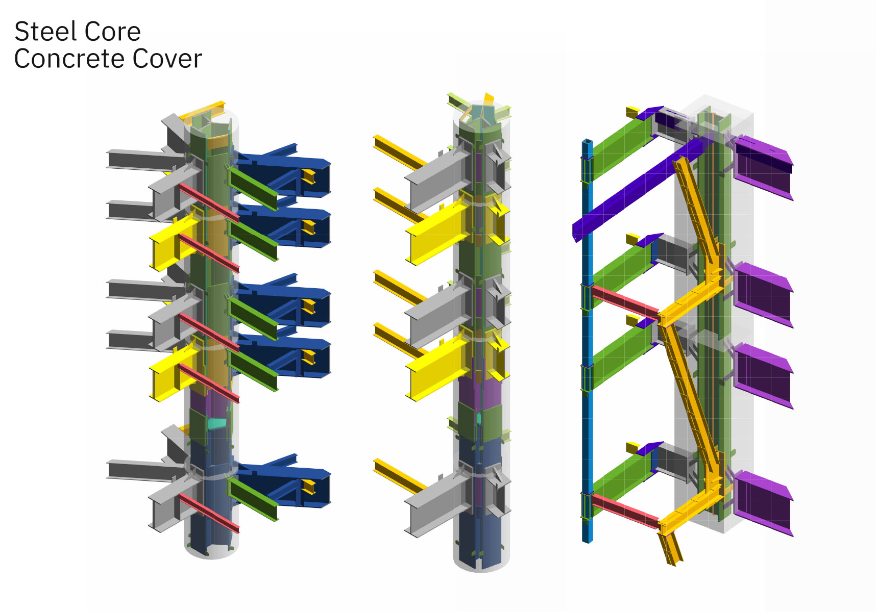
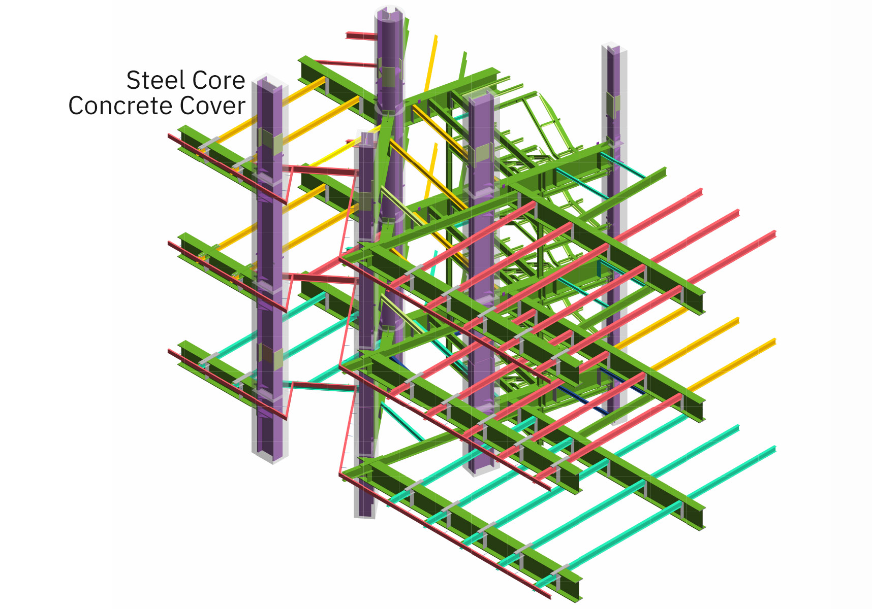
Concrete-filled steel columns (CFSTs) are represented with a steel core encased in concrete, including detailed connections to beams, slabs, and foundations. The model captures base plates, reinforcements, penetrations, and structural joints, as illustrated below.

This video presents the Revit Architecture Model using the Section Box tool, revealing detailed architectural elements of the architecture BIM model.
—Project-Specific Portfolio Disclaimer:
This project was developed as part of a collaborative design and delivery team. The materials presented on this page are selective, simplified, and modified representations, prepared solely for portfolio and academic purposes. The drawings, diagrams, and renderings shown may include simplified or cropped views, partial systems, and redacted or altered notes, dimensions, and technical information. The technical materials have been intentionally selected from non-final stages of the project, such as early design or execution-development phases, or from components that were later revised or significantly changed. Accordingly, the material presented here is non-final and non-buildable and does not represent issued, coordinated, tender, or construction documentation. It is provided only to illustrate the author’s contribution to the project. Authorship is limited to the specific work scope and contributions described on this page. Project copyrights and ownership remain with the respective client and/or firm unless otherwise stated. The full Portfolio Disclaimer and detailed copyright information applicable to this project are provided in the Legal Notice & Copyright section of this website.